Exploring Scan Staging With Reference Objects
-
As I taught my students in 3D design and printing classes, their goal should be to first LEARN their tools and then USE their tools.
And, that is exactly what I am trying to do with my THREE.
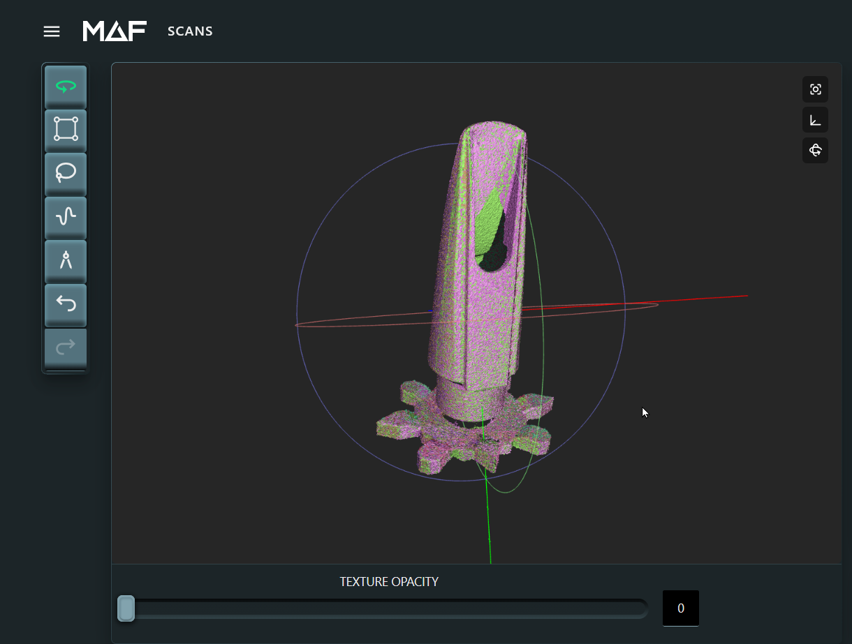
I don't mind limiting what I initially scan if experimenting with the THREE will give me insights that I can use in the future for many scans. That learning scan could be just about anything. In my case I'm using a saxaphone mouthpiece.
My goal is to explore and understand the THREE's feature based approach to alignment.
And, I am working under one assumption that may or may not be correct.
"Reference Objects should always move in relative position with the object being scanned as that object is changing orientation."
Objects often need to be re-oriented to scan all sides effectively. When this happens, I am assuming that all of the reference objects I am using also need to be re-oriented so that they always line up exactly in the same position relative to the scanned object. Therefore, creating staging tools (bases, swivels, props) that help us do that is a helpful
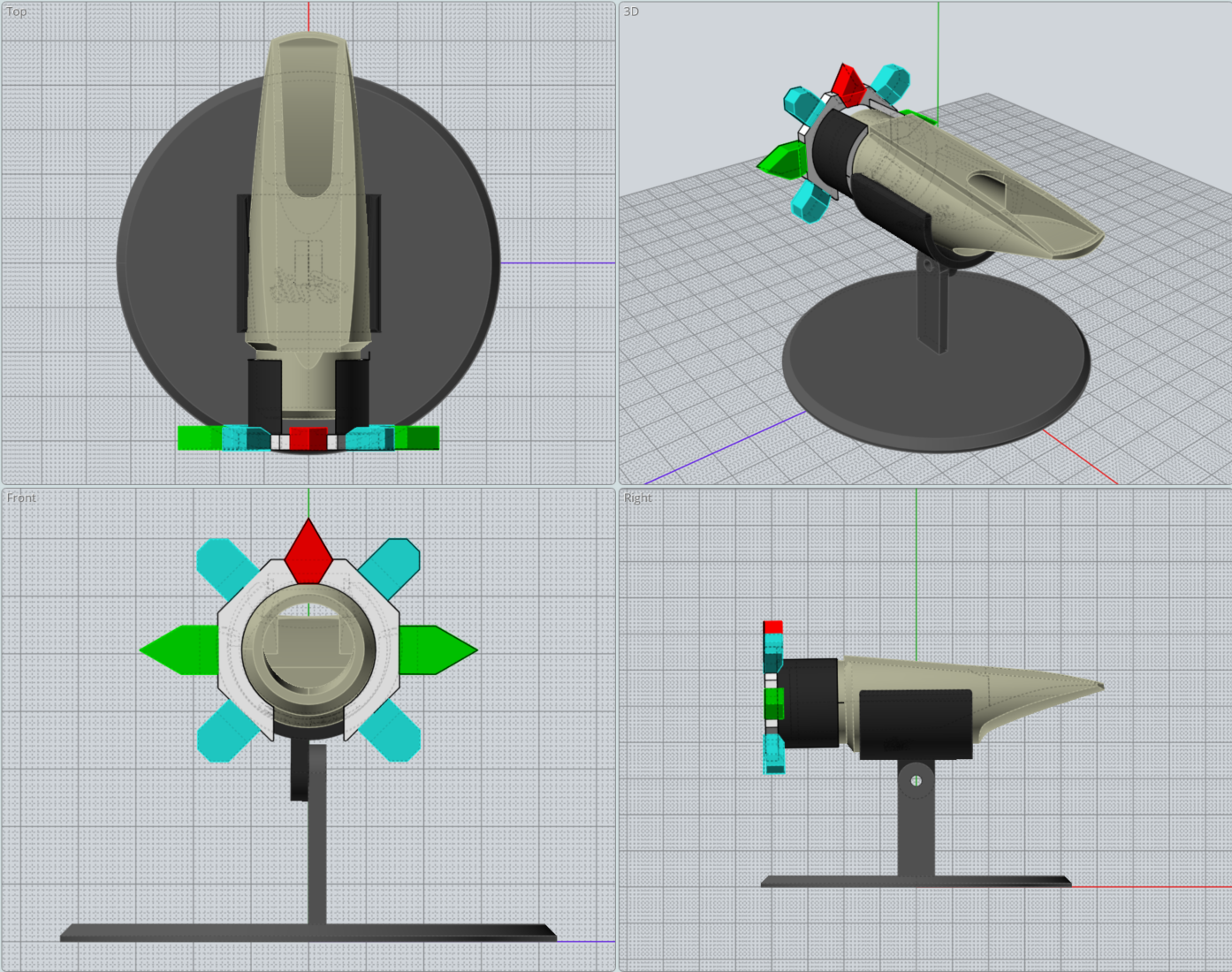
Since multi-color 3D printers are common now, that is what I am using to create my reference features.
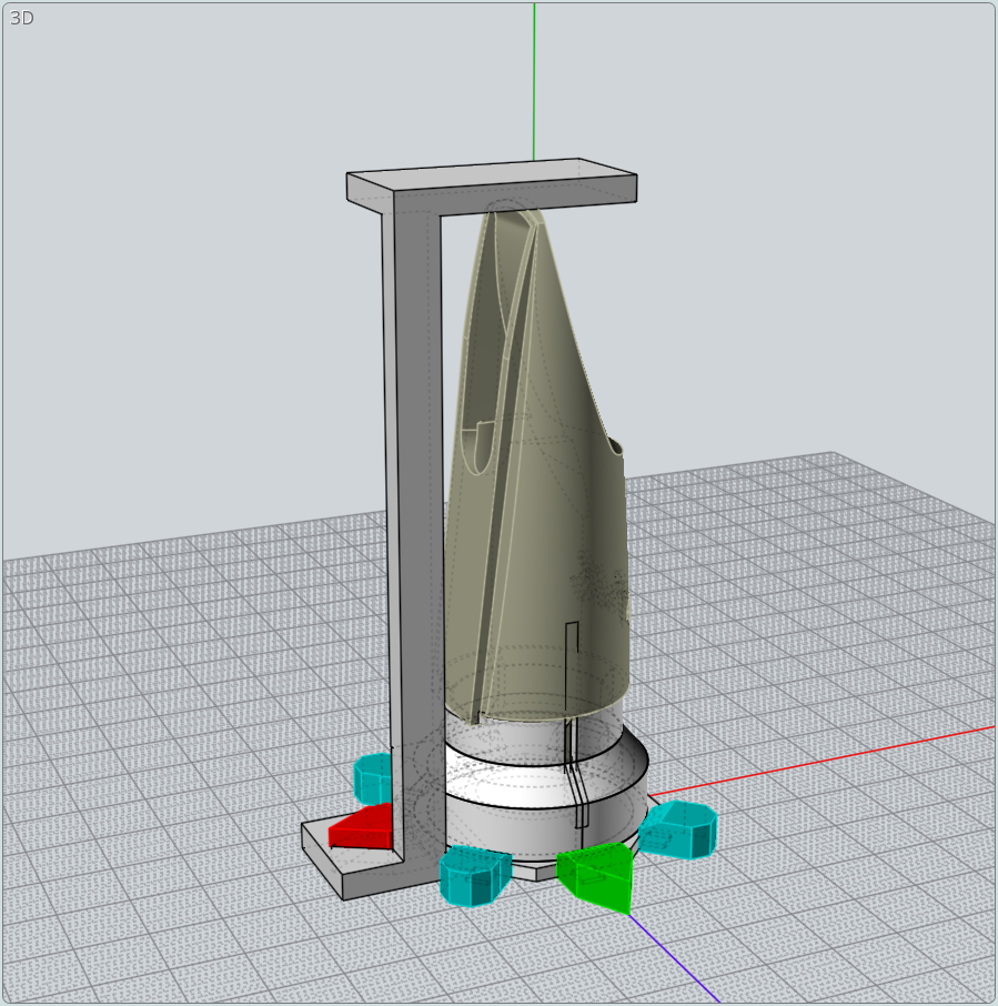
In this case, there is a base that swivels around two axes and a 'reference table' that slides onto the top piece so that it moves with the object being held.
Upright
Angled

While it works, there were some shortcoming in actual practice. The chief being that the short base limited the movement. The other being that the reference table features needed to be more pronounced.
-
In the first post, images showed that my initial staging attempt, while generally successful, had some limitations, like limited forward rotation to tilt the object. And, sometimes, it was difficult to locate 4 points for alignment because the reference feature object was a bit too narrow.
I thought it could be made to work better by inceasing the stand's height and making the features more pronouned.
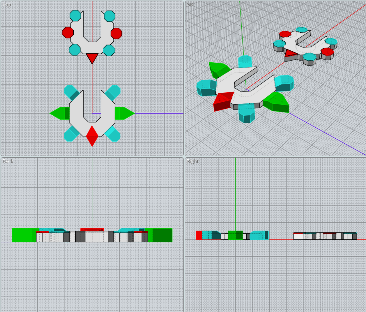
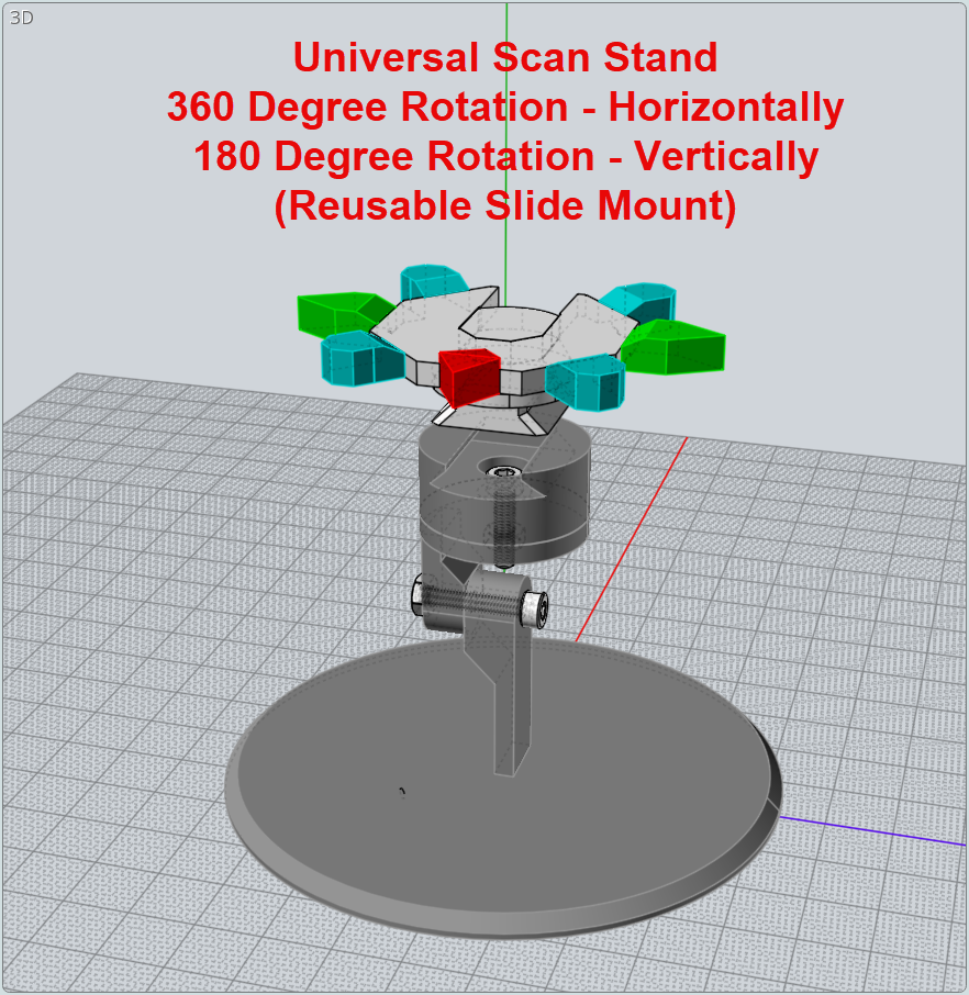
Increased Stand Height Results
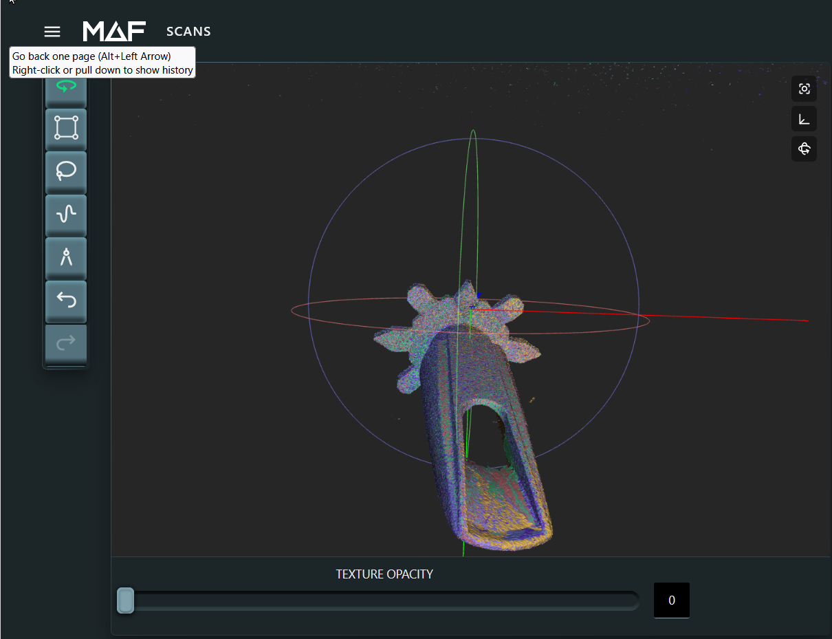
Just a little addition to the height of the base, allows for a MUCH deeper tilt forward for reaching deeper into the mouthpiece chamber while scanning.
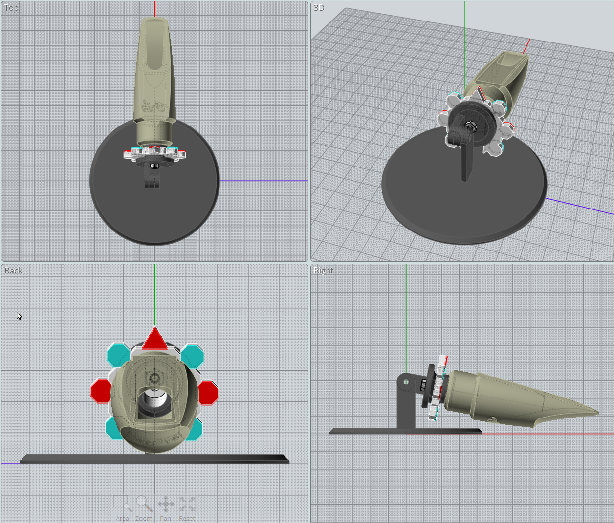
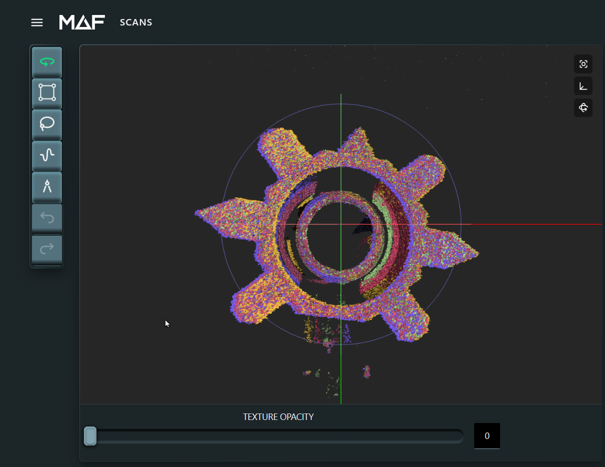
Changes to Reference Features Platform.
The first change to the feature platform was the width, making each feature protrude farther should expose more alignment points as the object is re-oriented. While only coloring the tops initially saved a lot of print time and generally worked, the new table's features are fully colored, which should help future scanning alignment. The two side features were changed from octogons to triangles to aid refining the point pick.
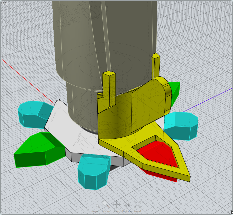
Addressing the problem of the Scanning the Bottom of the Object
The above stand and reference objects hid the bottom of the mouthpiece, preventing scanning. While capturing the bottom is not absolutely necessary, my goal is to learn how to address scanning challenges. In keeping with my assumption that the reference objects need to remain EXACTLY where they are relative to the object for aligning the bottom scan with the previous scans, I came up with this solution to try.
What will be important is to make sure the slipover scanning refwrence table is EXACTLY aligned, both in rotation and distance from the bottom. I'll be trying this new table this weekend. Hopefully, it will do the trick.
-
-
Thanks Vik.
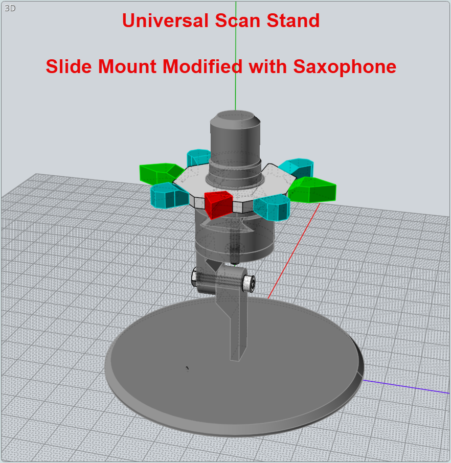
Actually this next step had you specifically in mind... making the stand universal so that it could be easily adapted for holding other things, like rigs.
The first step was to make the stand, itself, modular, with a slide-in mount.
With this configuration any clamp system could be used by designing a slide for each clamp. Here is the modificqation for holding a saxophone mouthpiece vertically. (Note an even larger reference table)
-
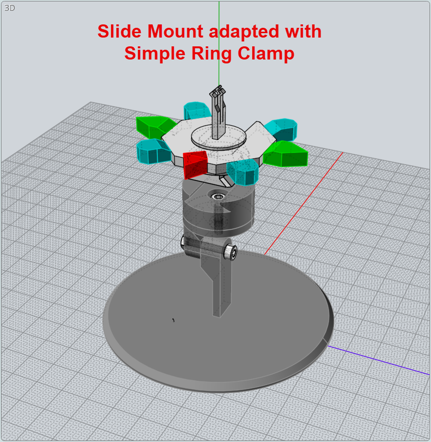
This next image shows how the slide mount could be easily modified to take a slide-in clamp for a ring. This is a just a quick design that may or may not work as hoped. But, it could be a place to start as one endeavored to create a reliable scan mount to be used for rings and smll jewelry.
-
This evening, I'm only scanning, and will leave all the alignment and post-processing until a later session. That's one of the beauties of using the THREE. Projects can be completed in stages, across multiple computers. I'm using a very old i3 Win10 notebook computer in my scanning work area and a fairly recent i7 notebook with a much better screen to do the processing from a completely different area from where the scanner is located.
A number of scan groups where taken. Here are just three of the groups.
Upright - 9 Captures / 360 degrees
Tilted 180+ Degrees to see inside the chamber
The Saddle slide-in support with the feature allowing capture of the bottom
-
One of the things I ran into was a tendancy to rotation the object directly, rather than rotate using the reference object. This inadvertantly caused the mouthpiece to slip off-center. While it could be aligned by sight, there was no way to ensure that putting it back was going to absolutely align with earlier scans.
The solution was to create an alignment and height tool that would ensure the reference object was in perfect alignment with the flat platform of the mouthpiece and also ALWAYS put back on the exact height. This had the added benefit of giving me the exact distance and design for the bottom alignment tool which slipped over the bottom of the mouthpiece.
-
It turns out that there is a better guage for ensuring that both types of reference objects are located precisely in the same place relative to the saxophone mouthpiece. The first guage helped to design the slide-on mount for the second reference object to be used with the side mount cradle. But, it could not accurately measure both distances after printing.
The solution is a guage that attaches at the bottom of the reference objects and locks onto the front reference feature. It the measures the distance from the bottom of reference object to the tip of the saxophone mouthpiece.
This guage can be used for each of the three saxaphone mouthpieces I will be using to learn about using scans for measurement and heat-map differences. So, it's worth the effort to get it right.
-
The more I work with the THREE, the better I like it. The time this journey has taken me has nothing to do with the THREE. It has to do with my desire to build a scan rigging tool that can used for many, many projects and do so most effectively. So, there have been many iterations.
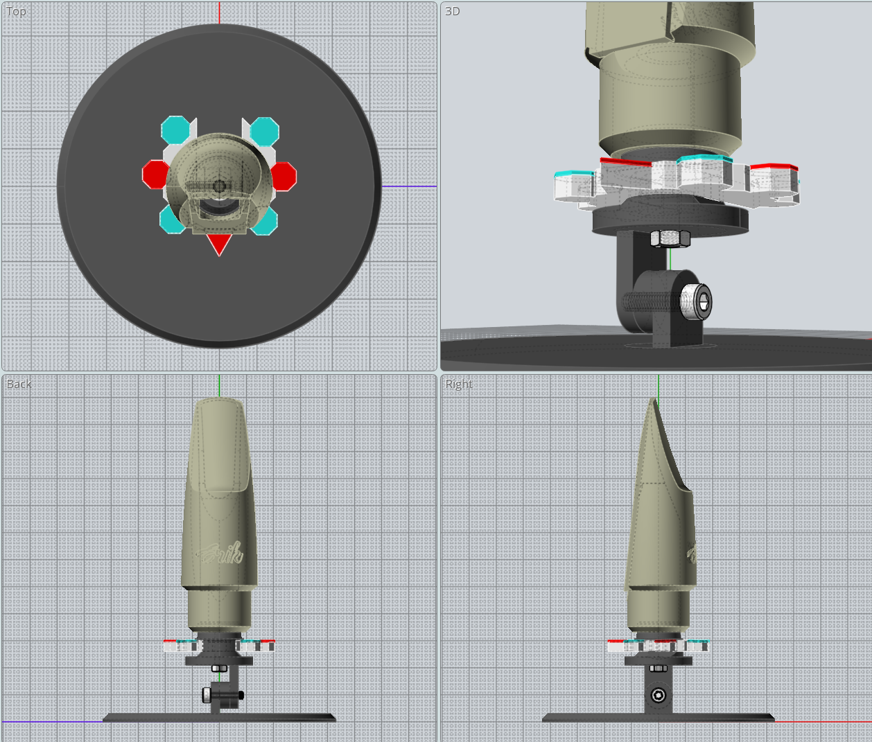
Here is what I think will be the final beginning of a system that will work with things like coins, rings and small parts.
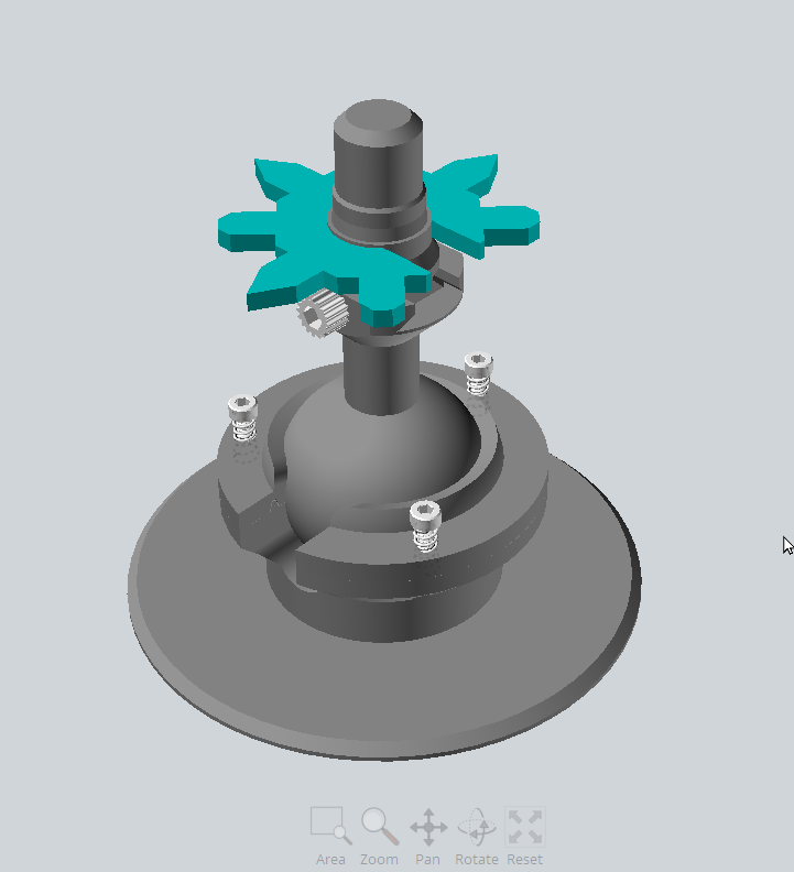
This ball pivot has worked extremely well and is the most versatile mount that I've used to date. It allows for exceptional motion and allows for very easy orientation changes. And, at all times keeping the reference objects to be used for point alignment in perfect relative locate to the object being scanned. It is allowing me very easy alignment of multiple scans. The ease of movement is contolled by loosening or tightening 3 knobs and can be completely locked down. Not only does it allow for various angles; but, full 360 rotation at any of the selected positions. I can upload STEP files or STL files if anyone would like to try using it. I will be ready to show the final scans in the near future. But, as you might guess, I am very happy with this scan rigging tool.
-
-
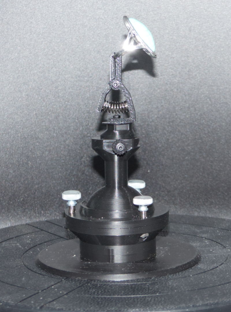
While post the last messages, it dawned on me just how easy it would be to design a spring clamp suitable for rings or coins, etc. It's not a great image; but, I hope it demonstrates how versatile the Ball Pivot system can be. Anything can mounted to the slide-in fixture. This first draft still needs a bit of work so that the position of the ring can be better controlled. But, it's an easy design to alter and prints very, very fast. The hardware required is two 2mm screws with nuts and a 7x7x20mm spring.
-
-
-
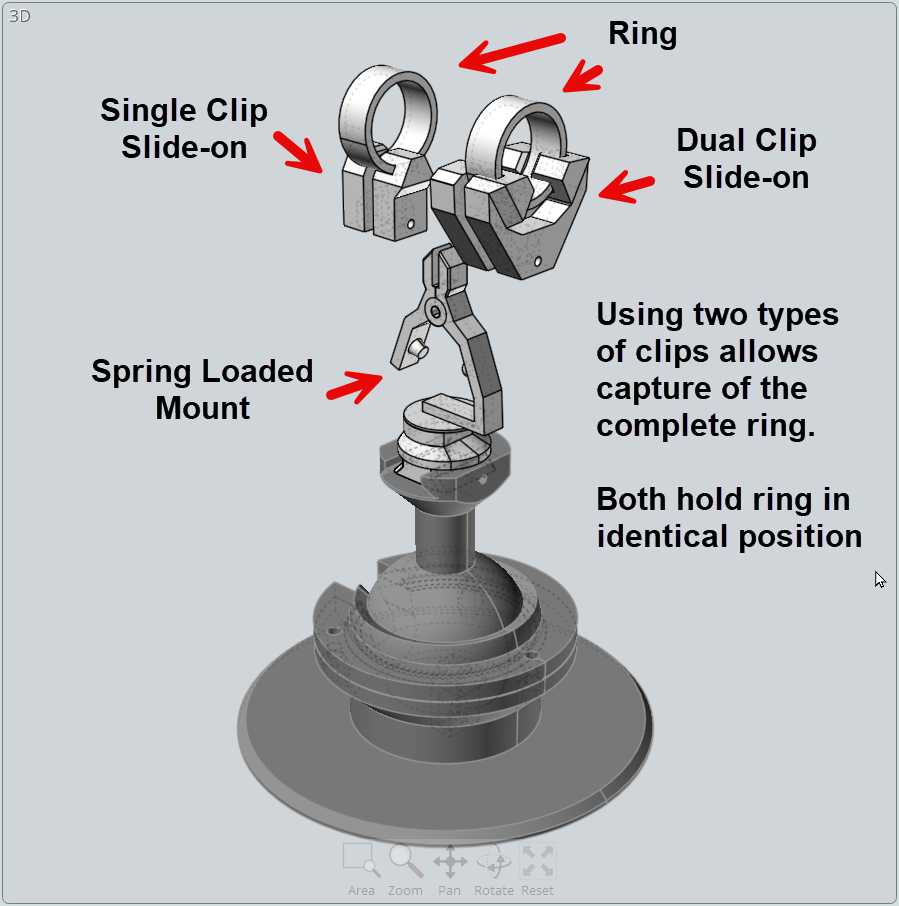
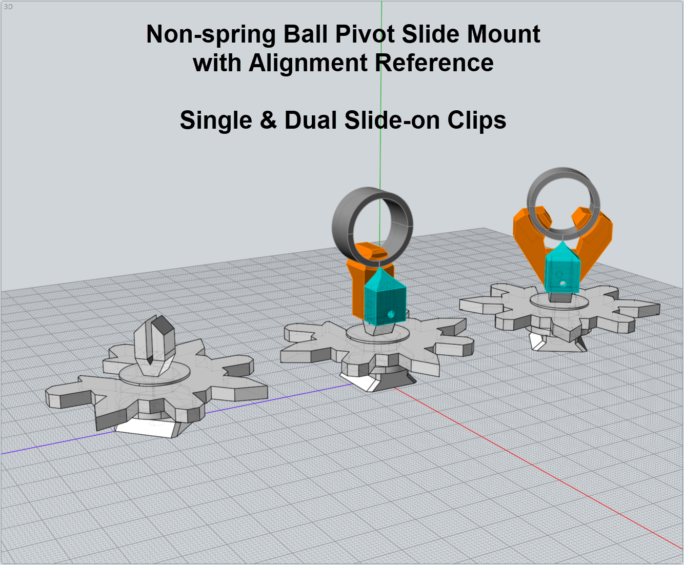
This image demomstrates the concept of using a spring loaded mount on the Ball Pivot base. Caps are slid onto each side of the spring loaded mount. One set of slide-on clips holds the ring on the bottom and the second set uses two clips located to allow access to the bottom area hidden by the single clip. So, the entire ring can be captured.
The slide-on clips generally onkly take about 15 minute print on a Bambu A1 Mini. And can be designed using any 3D application, including Tinkercad. I will document the sizes for customization when the clips are uploaded
 .
.
-
As I explore the concept of staging objects for 3D scanning, the idea of using rings as test objects seemed a natural.
I found a set of 19 rings on Amazon for the price of $9.99.
https://www.amazon.com/dp/B0BKVDYN6Y?th=1
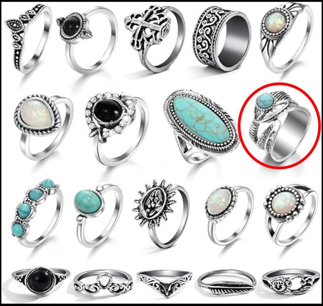
It contains several different styles that are perfect for using creating staging mounts for teaching critical thinking skills in an educational setting.
Building on the Ball Pivot mounting base, the goal will be to come up with clamps that hold each of the test rings, along with an optional reference object, to test the effectiveness of the system. My first test case is circled in red above. Since the goal is to be able to capture ALL of a ring, two test grips will be required... single and dual.
The first SINGLE grip, hides the very bottom of the ring, the ring slides into one side and a pointer is used to align the ring. A mark is placed on the ring at the tip of the pointer.
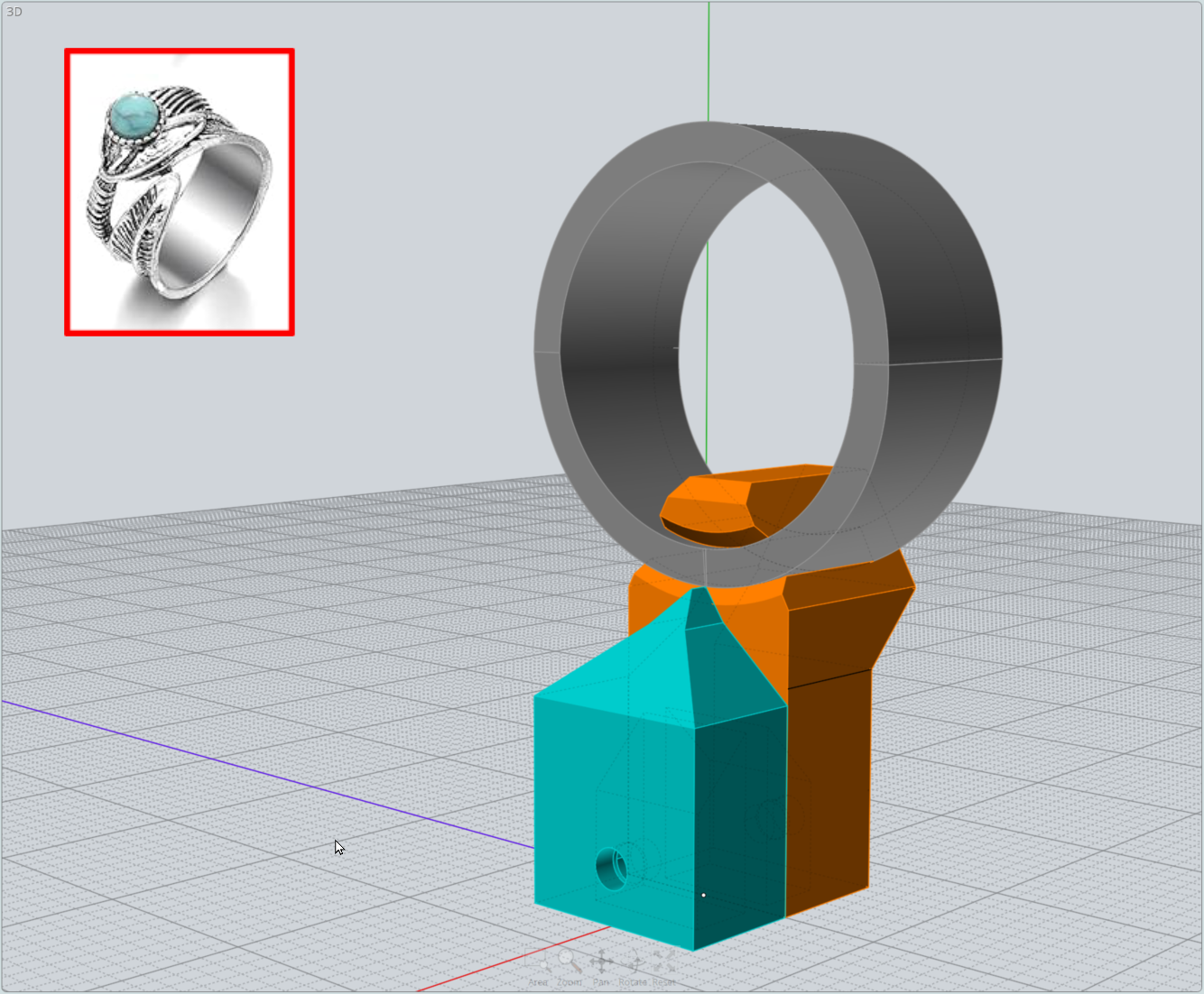
The pointer is also used with the Dual Grip.
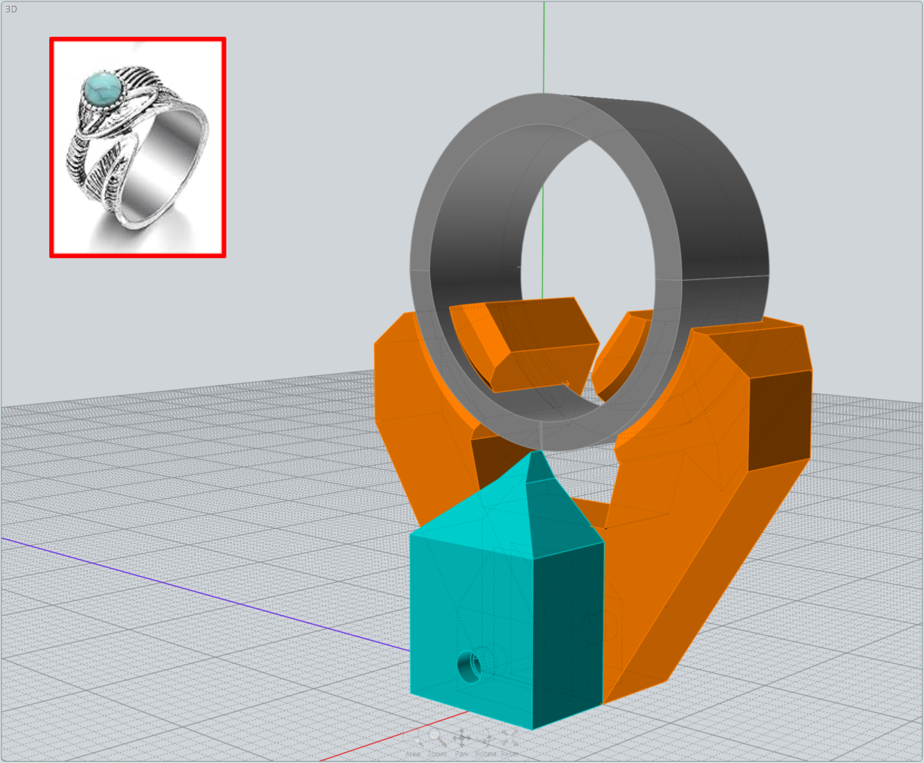
The pointer is used to make sure the ring is held in exactly the same location and orientation relative to the alignment reference object if it is to be used. To make it simple, a simple attachment to the Ball Pivot was created to accept the slide-on grip and pointer.
This has been created and tested; but, not yet used in a scanning session. Actually, with the first ring, the optional reference object may not be necessary, since there are so many unique features of the ring itself. In fact, it may work better without the reference object since the ring has a slight twist in its construction that makes it a bit difficult to ensure proper alignment between the single and dual mounts.
We'll soon find out. But, in any case, I am confident that this strategy will allow us to reach our scanning goal. Once, this has been tested, I will start a new thread focusing entirely on a designing a classroom strategy for exploring the THREE using cheap rings.
-
-
Taking the earlier Pivot Ball mounted Ring Staging clips a bit farther, it seemed that a spring loaded tool might be useful and more reliable when it comes to consitently aligning the ring with reference objects.
Once again, since the goal was to be able to capture the FULL ring, inserts will be used to swap single and dual grips with multiple scans. Here is a sample of Single Outside / Dual Inside inserts on a spring loaded tool that can be mounted directly on the Ball Pivot mount via holes in the bottom of the stationary side.
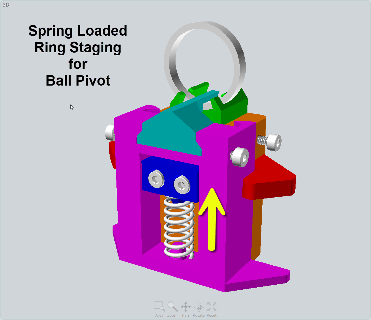
While I have not actually scanned with it as yet, I can already tell that I need taller inserts if I am going to be able to capture the bottom outside of the ring near the mounting. But, this is a trivial change that takes only minutes to redesign and print. I should be recieiving the new scanning spray soon, so we'll see how well it works.
-
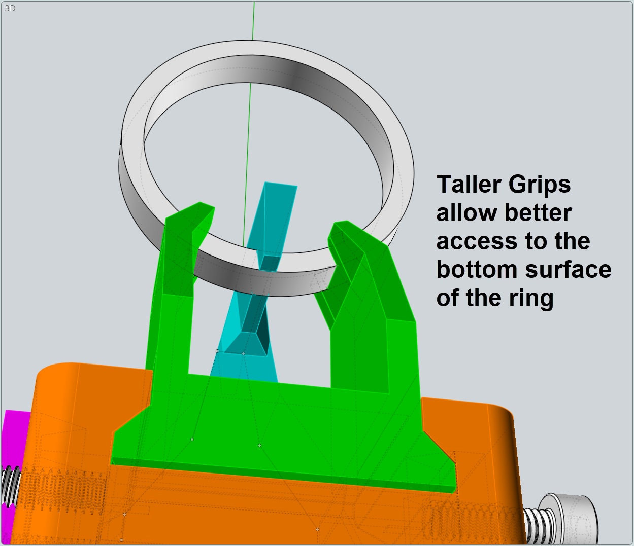
Experimentation with the insert ring grips is very easy with this system. Here is an image that shows the affect of making the ring grips taller. Note at taller ring grips allow for better capture of the underside of the ring. This is especially important with rings having a pattern that flows around the entire ring, like ring #4 in the image showing the ring set.
-
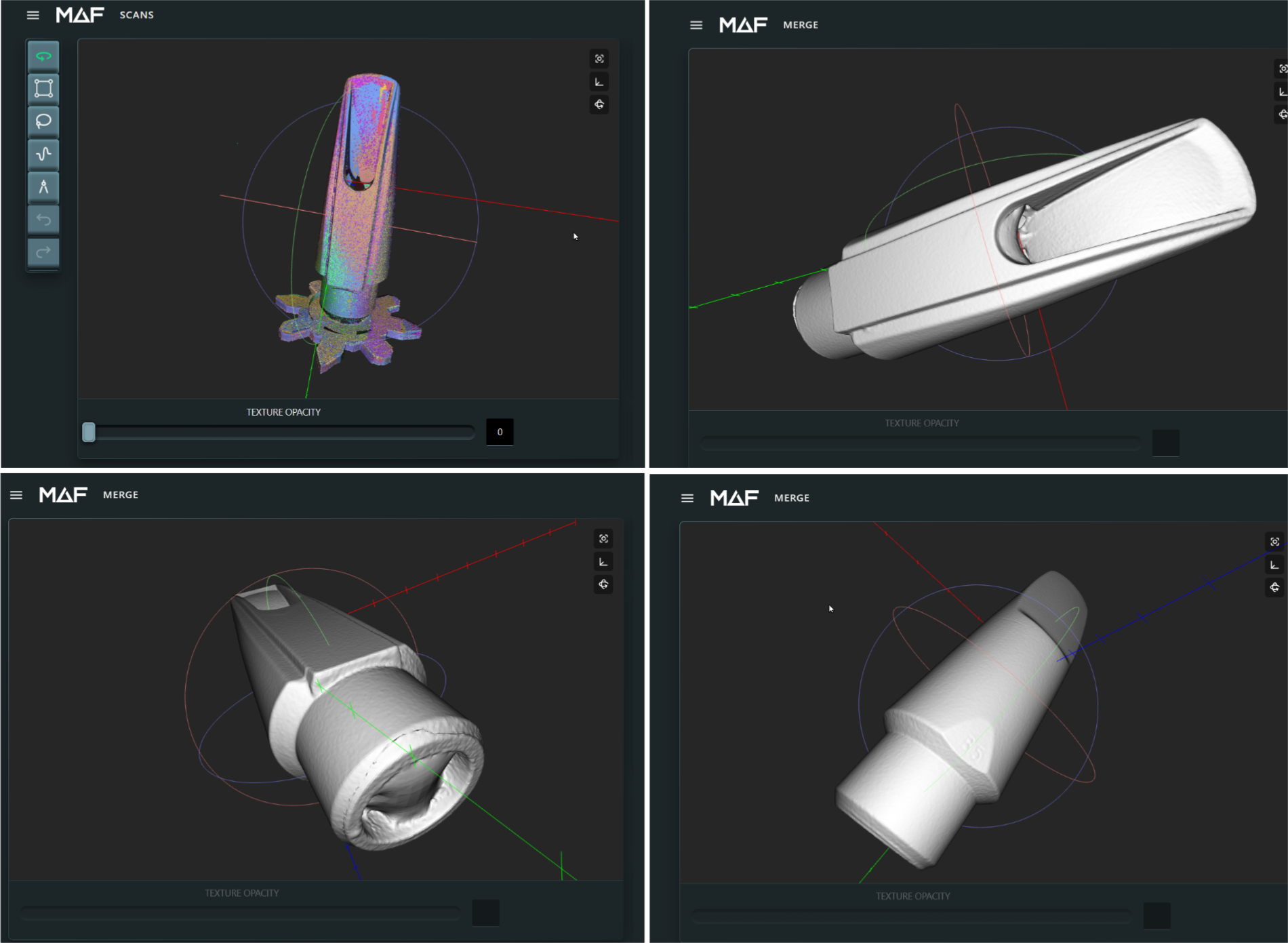
FINAL SAXOPHONE MOUTHPIECE RESULTS
The alignment went VERY smoothly using the reference object on the Ball Pivot stand. Here is the image showing the final scan results. Upper Left demonstrates the alignment of at least 9 sets of scans using two different Object Reference mounts, as describe earlier. I could not be more pleased. Of course, there were internal features that were unable to be captured; but, not more tha expected.
The THREE did a marvelous job of every step... capture, alignment, cleanup and meshing.