Exploring Ring Scanning Options
-
In educating any students; but, in particular, at-risk students, projects that promote critical thinking skills are highly desired. From personal experience, teaching hundreds of at-risk cadets from 4 different localities, there are few disciplines that offer as amny critical thinking possibilities than 3D printing and 3D scanning.
To be successful, ALL 3D scanning projects involve some form of strategy to achive the scanning goals. This is particulary true if the project's goals are set high.
As I was experimenting with scan staging, it quickly became obvious that finding ways to capture every feature of a ring, seemed deceptively simple. But, it's not. Some rings have full patterns that make alignment more difficult than others, etc. So, a high goal, when it comes to scanning rings is this:
Capture ALL features of a complex ring with perfect alignment in every respect.
Pursuit of this quest should result in multiple scan 3D staging designs. Most require some significan hardware, like screws and nuts. But, one of the goals I wanted to achieve was to design something that was almost completely 3D printed. The result was this design that still requires two 3mm bolts with nuts.
This Ring Ring relies on very thin >.25mm clear monofilament sewing thread to position the target ring near the center of the rotating ring. I will upload the files if it is successful in reaching our goal. (I ran out of time this weekend to try it.)
The monofilament is streteched between adjustable outrigger hangers by being wound around hubs and held in place with a locking cover. The question will be just how to run the monofilament to hold the target ring in place tightly with the least interference with scanning the featueres. Considering the possible combinations tests critical thinking skills to the max.
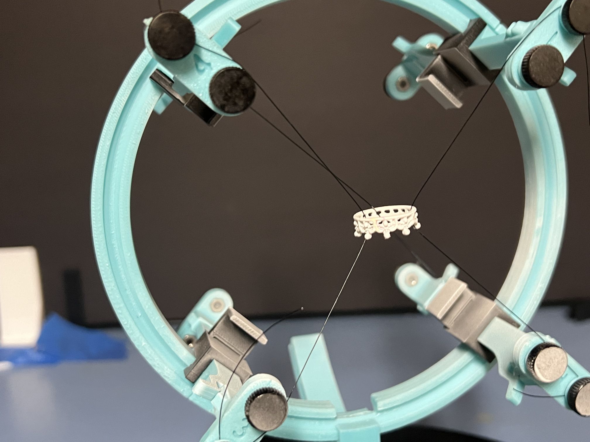
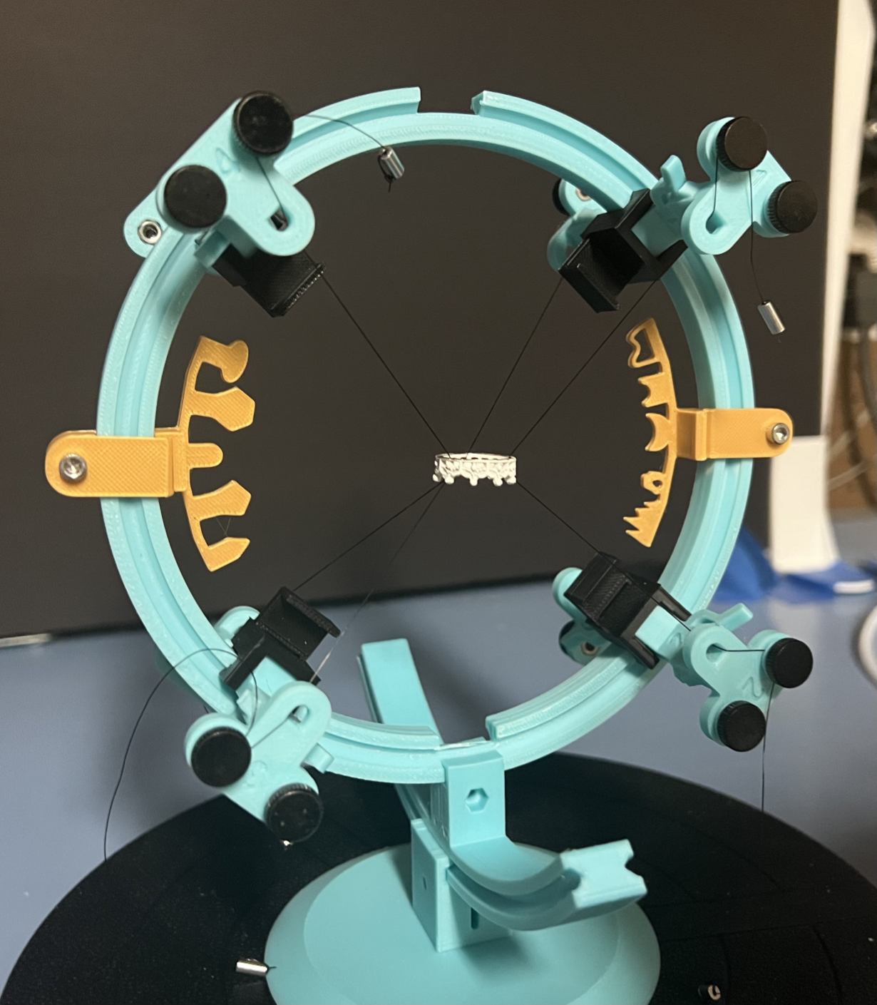
Here is The Ring RING:
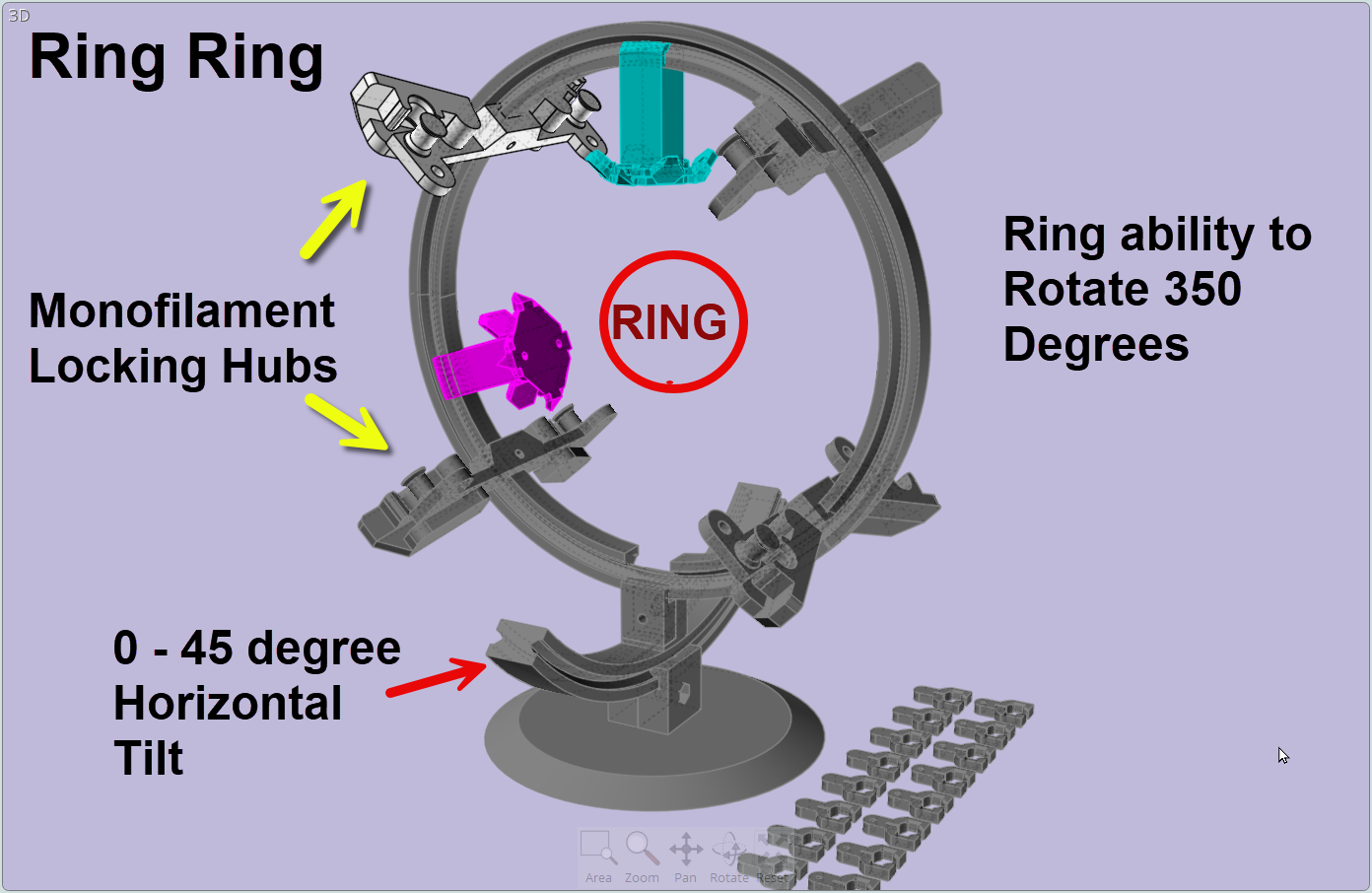
Note: The crossbeams can be secured in place with 3mm screws or the small 3D printed sliding locks in the lower right of the image.
Wish me luck.
-
-
I have finally gotten around to the point where I could confidently run a realistic test of a concept for a rig that would hold a ring for both spraying and scanning where the entire ring is able to be captured with reference objects for optimal alignment.
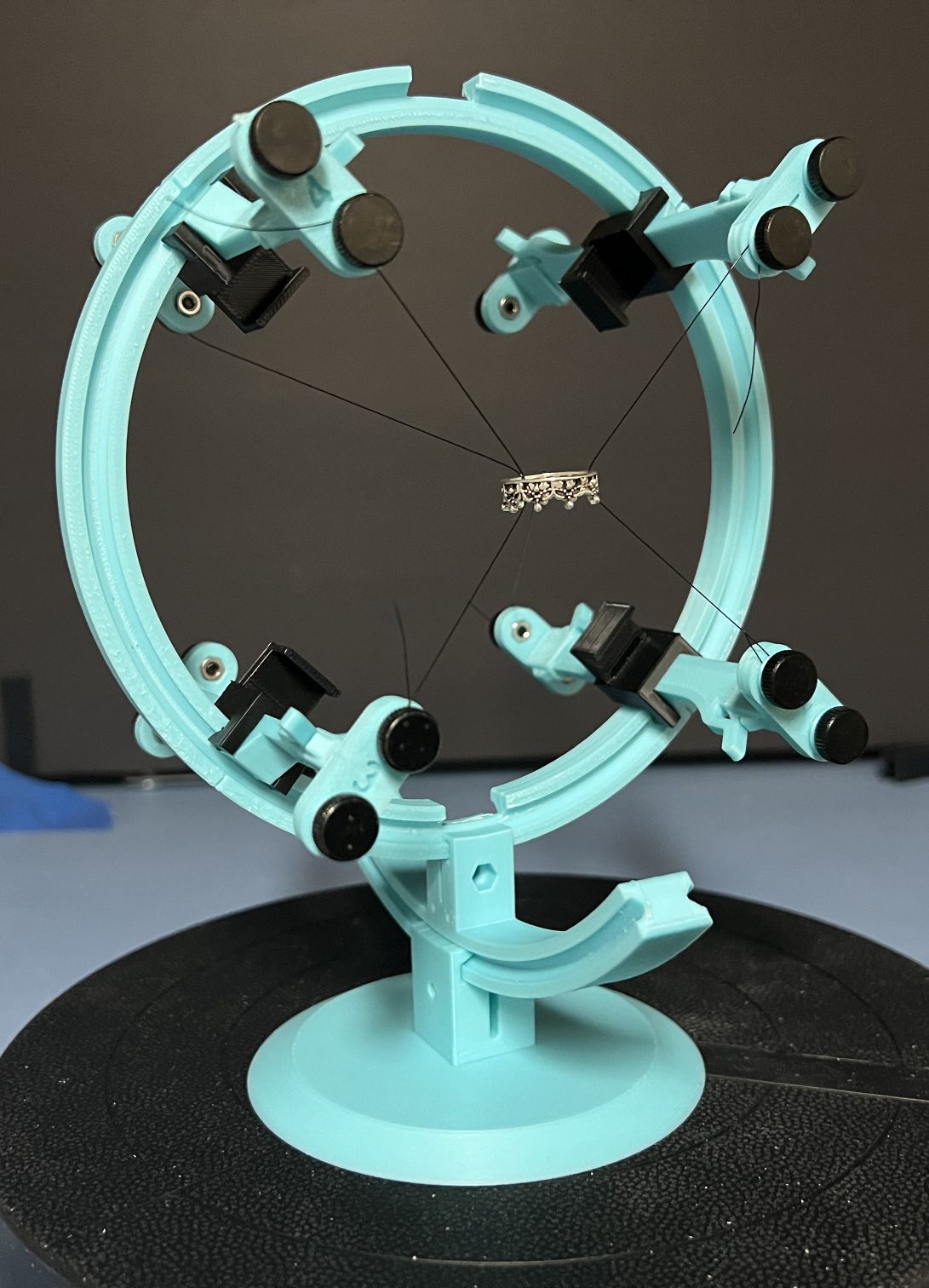
The basic system is a series of mounting posts. There are four in front and four in back. Monofilament is strung from one post, through the ring and to another post. In my first test, three strings were used. Two in front and one in back.
Note that there are two screws (or capstans in a screwless version) at each mounting point.
The reason for this is that spraying corrupts the string, making it visible in the scan.
The second screw allows us to string new monofilament in exactly the same configuration BEFORE removing the corrupted string. We replace all the sprayed string and replace it with new, clean string.
The new string is less likely to be captured by the THREE. Notice that the ring remains in just about the exact same place and orientation. The ring does not move since the strings are pulled tightly.
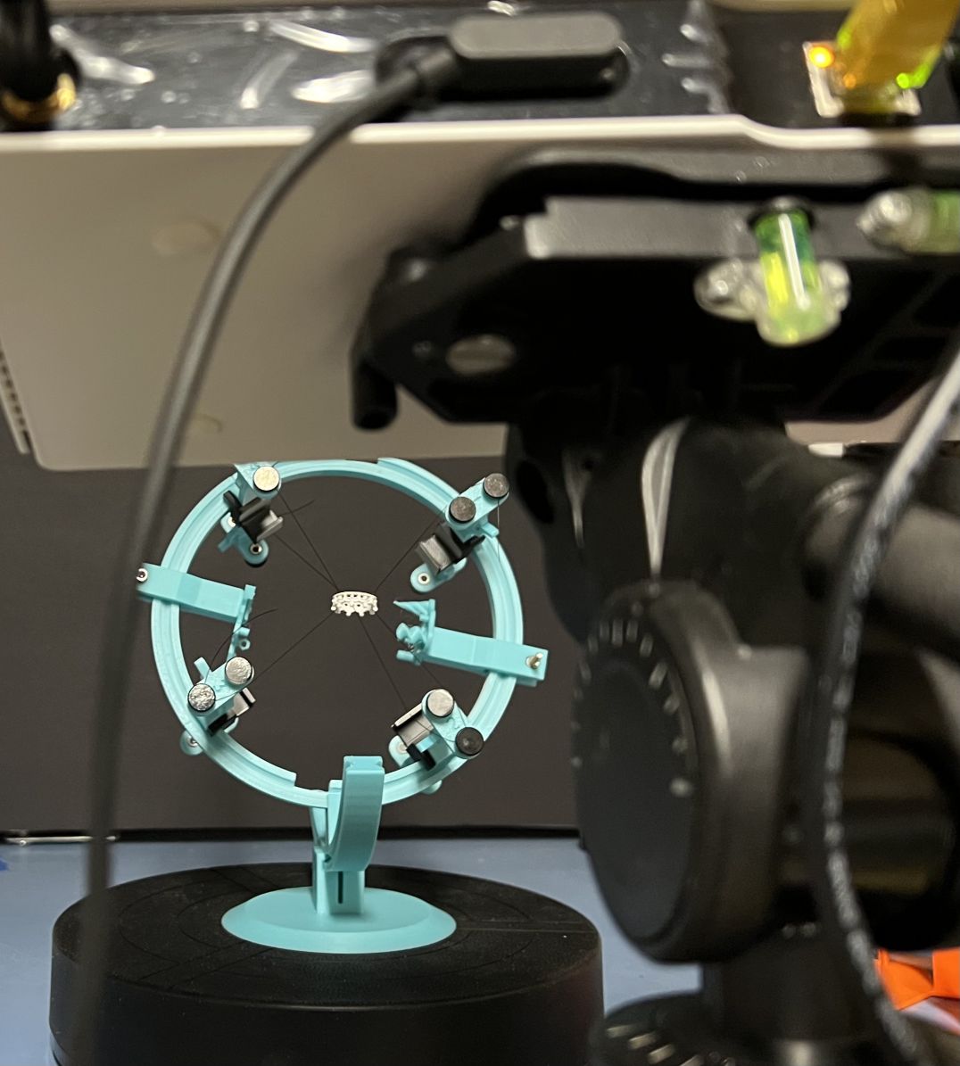
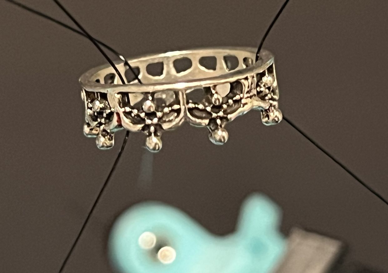
The previous image gives us a hint as to just how small the ring is relative to the THREE Scanner. Here is the actual scan with the THREE measurement tool.
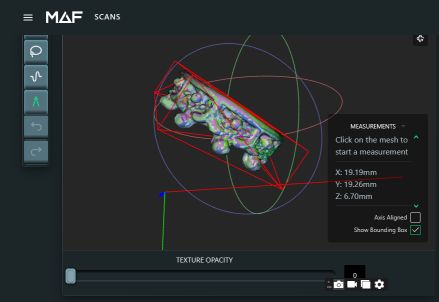
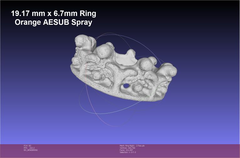
Having to spray the ring results in a rougher than hoped-for surface. But, that is only because the THREE is capable of incredible resolution! Here is the final scanned result with two 13-scan passes. Note the precise alignment between the scan groups due to the included purposefully designed reference points.
EVALUATION: The concept works exactly as I had hoped. But, it can be improved. The connectors on the tested rig were vertical (up and down), they will probably be easier to use if horizontal (side to side). While the reference objects worked exactly as hoped, they can be improved by better placement and layout. As it is now, they block the view of the scanner more than they should. Because the system is modular, both of these improvements will be trivial to design and replace.
All-in-all, I am VERY pleased with the first results and look forward to making the improvements and running a second test.
-
-
Thanks, Christian.
I have made a few changes including making the anchors horizontal and refining the artificial reference points to be less intrusive. I have not had time to test it yet. But, I have remounted a ring and it is definitely easier to use. I have also refined my strategy in dealing with monofilament line. I found some aluminum sleeves that are much easier to deal with than my initial experients with using glass beads. No need for glue since the sleeves can be tied to the ends of the monofilament. That makes life a whole lot easier! LOL!
-
-
-
-
I can only say that with my limited tests on a very small object (20mm diameter) using 3d printed reference object, alignment has not been an issue of any import. The auto align with the THREE, with reference objects, has been excellent the bulk of the time. But, Point Pick alignment has been stunningly effective. More on that later. :)
I really came up here today to say that, based on limited testing, I think I have FINALLY designed a rigging system for small objects like rings that I was seeking.
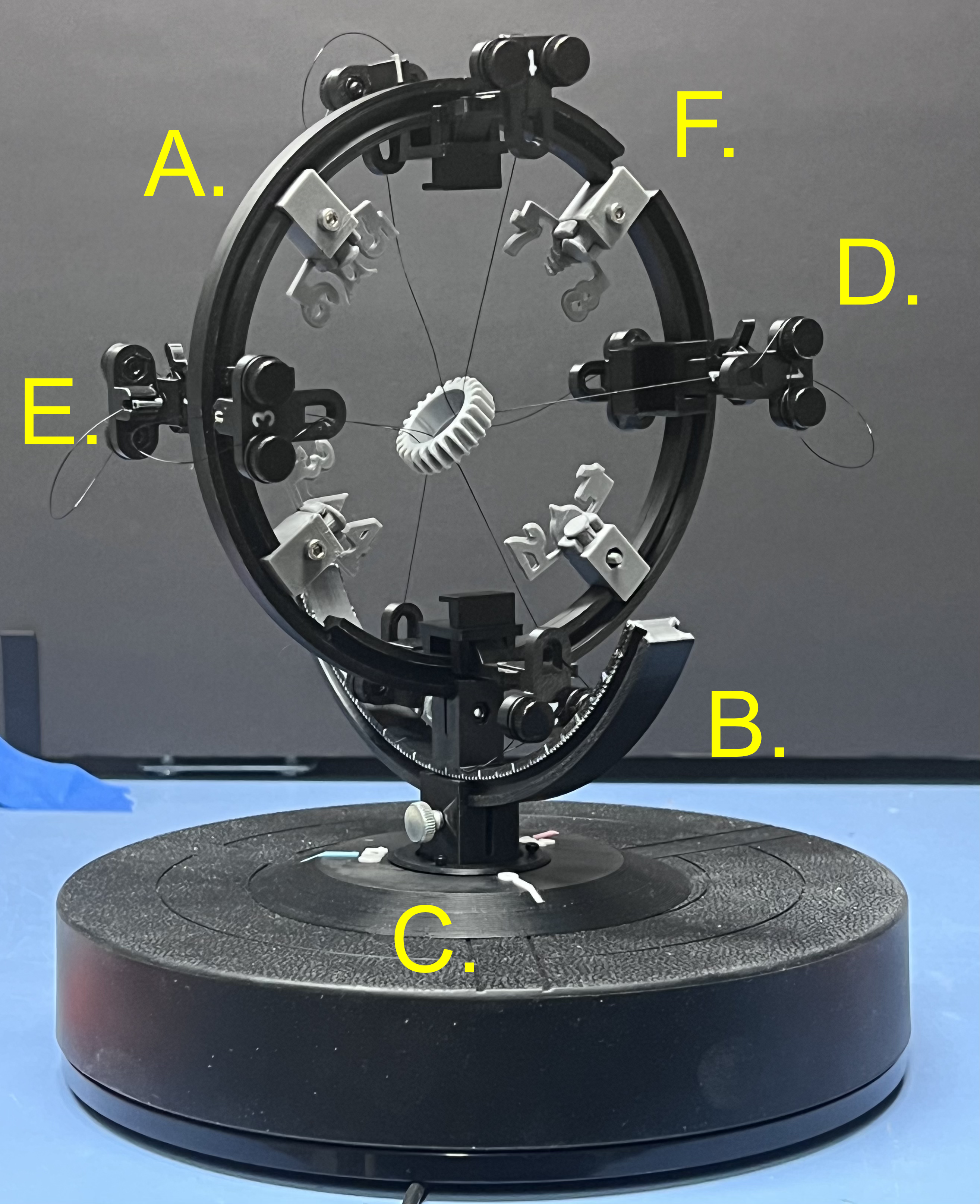
Here are the features:
A. 360 degree rotating ring that holds all the mounting points and reference objects.
B. 120 Degree rocker for tilting the ring forward and backwards with 1, 5 and 10 degree markers.
C. Base with markers a 0, 120 and 240 degrees markers to help with ensuring overlap of scan groups.
D. Dual Mounts (4 front, 4 Back) for attaching monofilament lines that hold the target.
E. Hidden insert snaps for holding the aluminum sleeves used at the ends of the monofilament lines.
F. Reference objects that can be relocated or rotated as needed.
All of these features, together, give us an excllent platform for helping the THREE's light projector reach every nook and cranny of a of the target. The goal is to present that target in any orientation necessary to reach hard to light features. And, to hand the THREE reference shapes that are so definable that matching shapes between scans have the necessary matching characteristics.
The latest version moved to using numbers are reference objects. The reason for this is that it is easy to see the front/back orientation of numbers or alphabetical characters. A number, from the backside, is reversed. Front/Back orientation be shapes like triangles or pentagons, alone, can be ambiguous.
By the way, een though the monofilament line is VERY thin, it holds the ring in a rock-solid position, with NO movement between scan groups, etc. Routing the lines objviously is key; but, given the number of mounting points, there are few, if any, limitations.
I would have posted my first tests because I am very happy with what I see. But, I did those before creating the new number reference objects and my front/back tilt was too limited. This left two areas inside the ring not reached by the light source of the THREE and my goal is near perfection. It was VERY close to my goal; but, not at the standard I know this scanner can achieve. I have used enough scanners to know what is incapable for a scanner or what is being missed by me, not the scanner. And, that is a very important distinction. Light travels in a straight line... so we must ensure that we present our target in every way necessary for that light to reach every feature in our target that has any possibility of being reached. This has been one of the most enjoyable projects I ever undertaken. And, I have learned a lot.
I really don't think having the ability to use marker dots would be any more helpful at all, given what I have experienced so far.
-
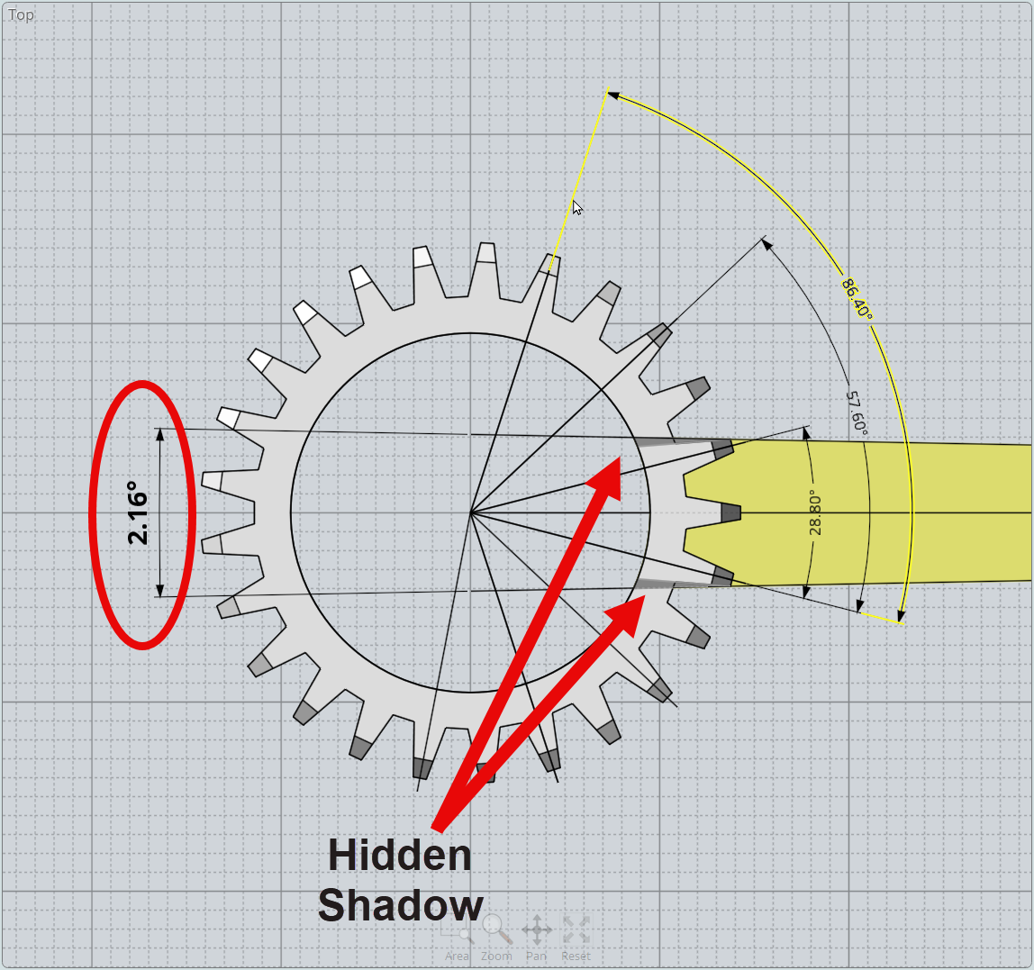
I should have pointed out that my test "ring" features 25 'facets'. This weird number was purposely chosen to make the math of selecting scan counts and angles more difficult. I spent some time making sure that the design presented plenty of shadow situations to the THREE's light engine.
We always have to remember. Light travels in a straight line.
I really wanted to give myself and the THREE a true challenge. Figuring out the number of steps in a scan is based on the minimal capture area without a shadow. In this case the rotational requirements are based on fairly small angles before a shadow occurs.
-
Quests are ALWAYS interesting! LOL!
I was perplexed as I examined the THREE scans of the 3D printed ring I am using for testing and saw the surprising "ERRORS" between the peaks. This streaking marked by a blue circle, I surmised, just should not be there.
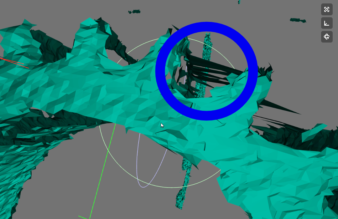
But, I have also learned, that it's easy to jump to conclusions about a product's performance when the real reason may be somewhere else. And, that was case in this instance. A close examination of the original print revealed the real reason for the anomalies!
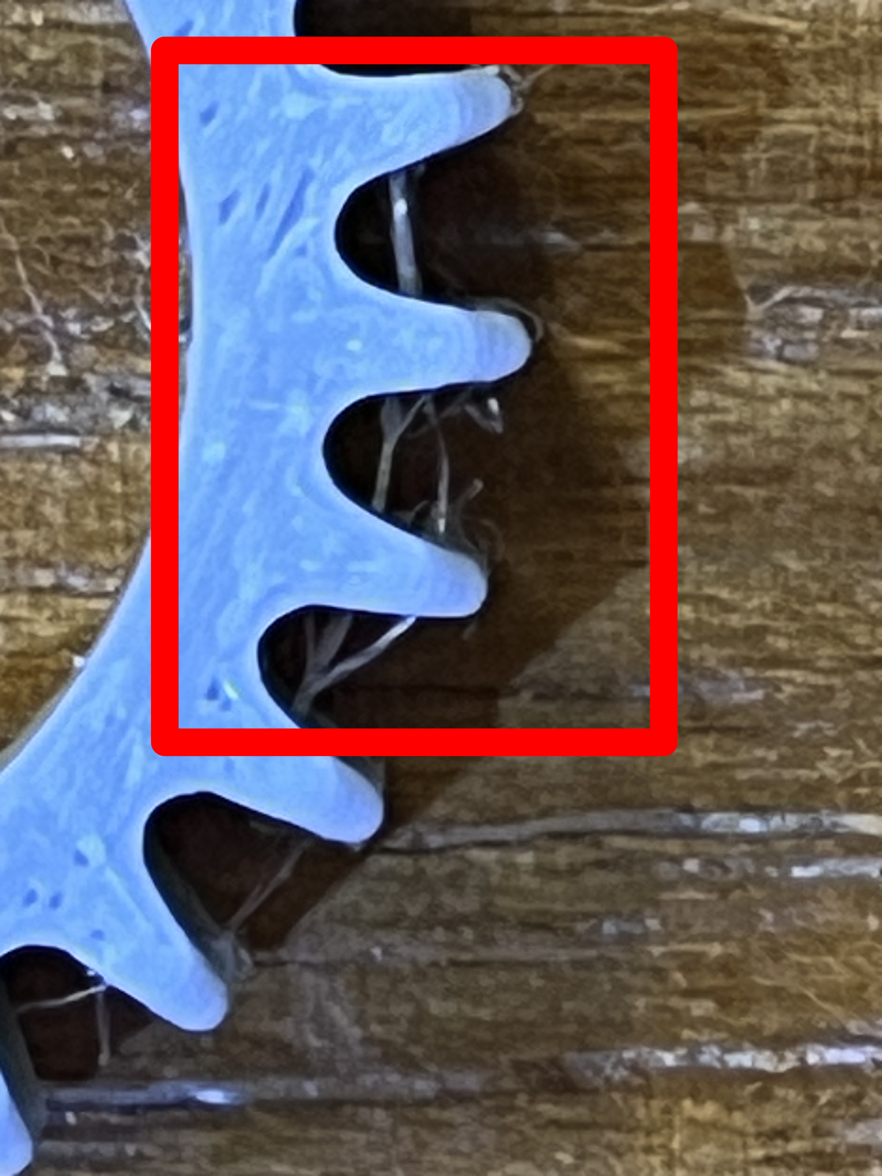
It turns out there was some very fine stringing I had not noticed before. The problem was not that the THREE was creating phantom features. The real reason for what perplexed me was that the THREE was capturing errant stringing that my own eyes, without magnification, could not see! That is great detail!
So, I am going to clean up the target print with a rotary tool brush and make a fresh start at moving forward. Not all quests move forward smoothly; but, all quests are well worth the trip when we learn new things along the way. I learned, in a weird way, just how detailed the THREE's resolution is.
-
I continue to optimize the design of the ring staging system. But, I have already proved to myself that this has been a worthwile project that is returning excellent results. The initial tests have proven that the system allows us to see the test "ring" from every necessary angle to get complete coverage. It has also demonstrated the incredible accuracy of the THREE. As mentioned before, the 3D printed ring had to be cleaned of stringing because the THREE picked up the wisps of filament I had not noticed.
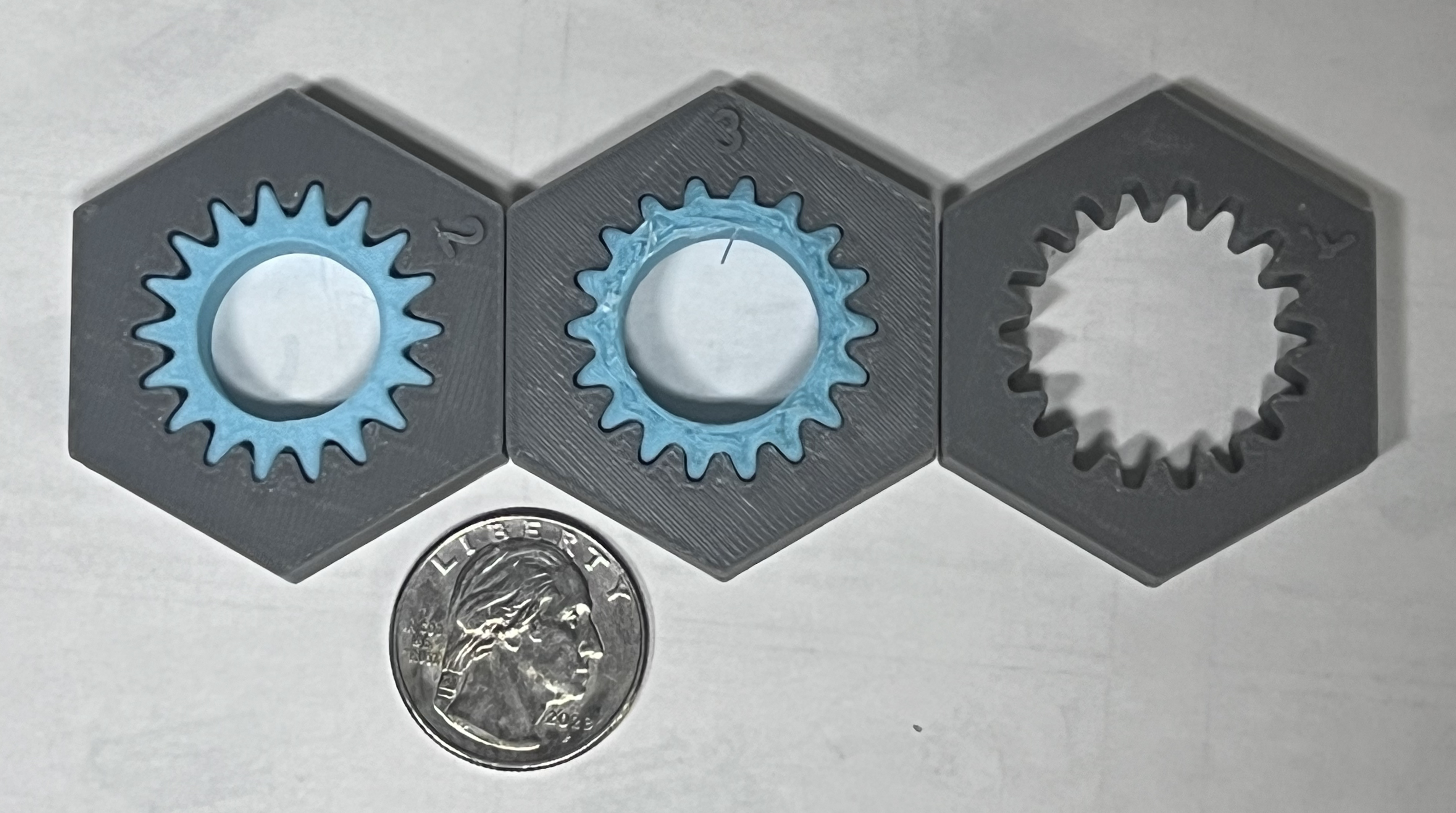
In doing clleaning the rings I inadvertantly swapped an 18pt ring that had also been printed and mounted it by accident. So, the samples to be shown today where not my preferred 25pt ring; but, the a8 point ring. In both cases I had printed out test objects into which the rings could be inserted with offsets of .2mm, .3mm and ,4mm to be used in comparing the original and scanned results. Here are my initial results.
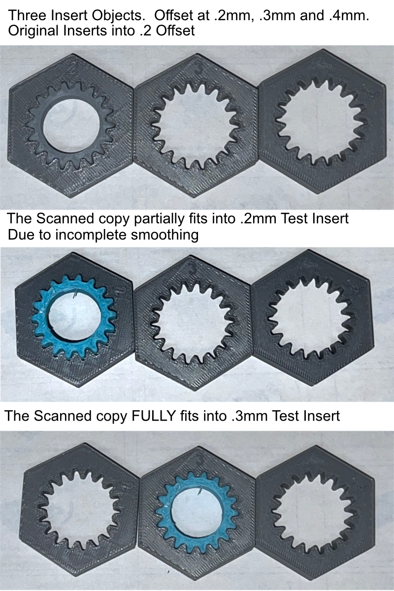
As you can see, as expected, the original grey ring fits perfectly into the test target that is offset by .2mm. While it is difficult to see in these photos,. the scanned (cyan) ring almost fits into that same test insert. It can be put in about halfway. The size and shape is nearly prefect; but, I did not get the smoothing quite right. However, the copy DID fit perfectly into the test insert object that had an opening just .3mm offset. I am absolutely certain, that with a bit more experience with the smoothing function built into the THREE's system I can achieve that goal of an EXACT match of the original. And, I am equally certain that the results, based on my research, would have been no better using a $6000 scanner built for scanning rings. And, The output of both can always be smoothed using 3rd party software. I am VERY pleased.
I continue to refine the staging system to remove as many impediments as possible from blocking the view of the THREE as it does it's work. So, I hope to have more soon.
-
When I started this ring staging project, I set a goal of creating a copy of the 3D printed "ring" using the THREE scanner that was functionally exact in size and shape. I realized that the scanned surface might not be as smooth as the original. But, I hoped I would be able to realize a scan that would fit into a hole the exact size and shape into which I could insert the original.
My first try, as documented earlier, came close to achieving that goal; but, required a hole oversized by .1mm. It only partially was able to fit into the same hole that fit the original. I made some significant changes to my ring staging system that permiited the THREE to see more of the ring without interference of the staging mechanism's structure. Thos changes were finished Christmas Eve morning and I was unable to test it due to travel for the holidays.
This afternoon, I was able to test the new staging design and here is the result.
The ring PERFECTLY dropped into the hole that fits the original. I did have to use Meshmixer to flatten the top and bottom so that Bambu Studio would not demand to use supports. But, NO corrections to the ridged pattern, either peaks or valleys, were required. That being said, I would like to see some more comprehensive smoothing options in future releases. But, for now, I consider the goal I set for this project to have been resoundingly reached.
The most important things I learned on this quest was the importance of using reference objects that have a recognizably distinct front and back shape. Numbers are perfect reference shapes because most numbers in most fonts are distictly different as we view them from the front or from the back. This was essential to the success of this project that required multiple scans from every concievable angle. The letters made using the "Point Pick" method of alignment a piece of cake and highly reliable. I also learned to respect the scan "Normals" when choosing which scan to use as the anchor for each newly aligned scan since scans with like normals were easier to compare due to lighting.
-
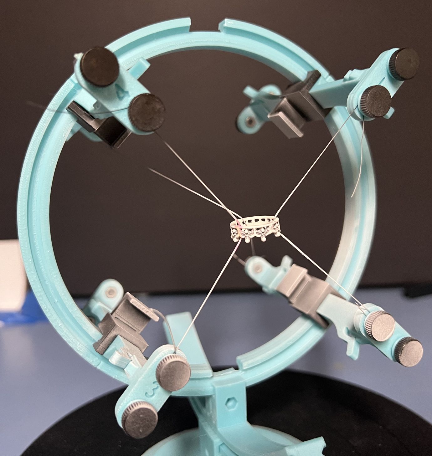
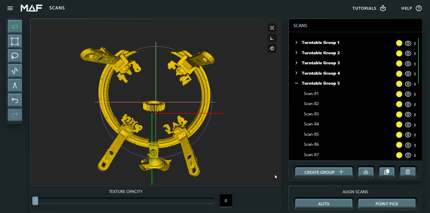
This is a screen capture of the Ring Staging system in use. Note that I replaced the rocker base for a pivot ball system that was less intrusive for the THREE scanner. Also, note the numbers in 4 different locations used for thr "Point Pick" alignment operation.
The dual mounting ends were replaced by single point mounts. Again, to reduce the interfence for the THREE's camera. The ring remained stable at all times, so while monofilament still remains the curse of the devil to handle, it did proved as effective as hoped!
-